Depth buffer (in depth): How to implement a fog post-processing effect in three.js and react-three-fiber
Abstract
Welcome to our deep dive into the world of Three.js and React Three Fiber, where we unlock the secrets to elevating your web projects with depth buffer and post-processing effects. If you're passionate about creating not just visually appealing but truly immersive 3D web experiences, you're in the right place. This guide is crafted to walk you through the essential techniques and best practices, making these advanced concepts accessible and actionable. Whether you're aiming to enhance your current projects or exploring new creative horizons, join us as we explore the steps to bring depth and interactivity to your web development endeavors. Let's dive in the depth of the depth buffer (I need to stop with the puns, I cannot help it). 🤿
Camera theory 🎥
To understand how the depth computation works in 3D, we need to look at the camera theory itself first.
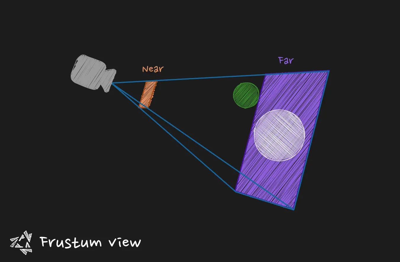
The camera has what we call a view frustum. This frustum is some kind of truncated pyramidal shape that is placed in front of the camera. Any object that is outside of the frustum sees its fragments discarded, (if you prefer, its polygons). That is particularly convenient to avoid computations on objects that are very far away or behind the camera for example.
From this truncated pyramid, we can extract two features: the near plane and the far plane. These two can be more or less distant that leads to a change in term of the distance that the objects are discarded. Often when you zoom out the camera and you see objects disappearing too soon, you have a far plane that is too close. Increasing the distance will help, but be aware of the performance cost. If close objects disappear too soon to your taste when you get closer with the camera, you may want to bring the near plane closer.
You will see that the relation between the quantity of movement of the near plane and the quantity of movement of the far plane that you need to use to get expected result is very very different due to the nature of the these two planes.
A slight modification of the near plane has dramatical effects on the scene. (To give you a magnitude, passing from a distance of 1 to a distance of 0.1 can really change everything in term of object discarded). For the far plane you can use greater values (like passing from a distance of 150 to a distance of 1000).
Keep that in mind, it will have an importance when discussing the depth buffer.
Depth buffer 🤿
Also called Z-buffer. It is a type of buffer containing data about depth of objects in the 3D space. It helps for example to get this information to know which objects is occluded another object. That way we can discard polygons that are not seen from the perspective of the camera. It is also a useful element when you want to create post-processing effects. You can for example create fogs, outline shaders, and so on.
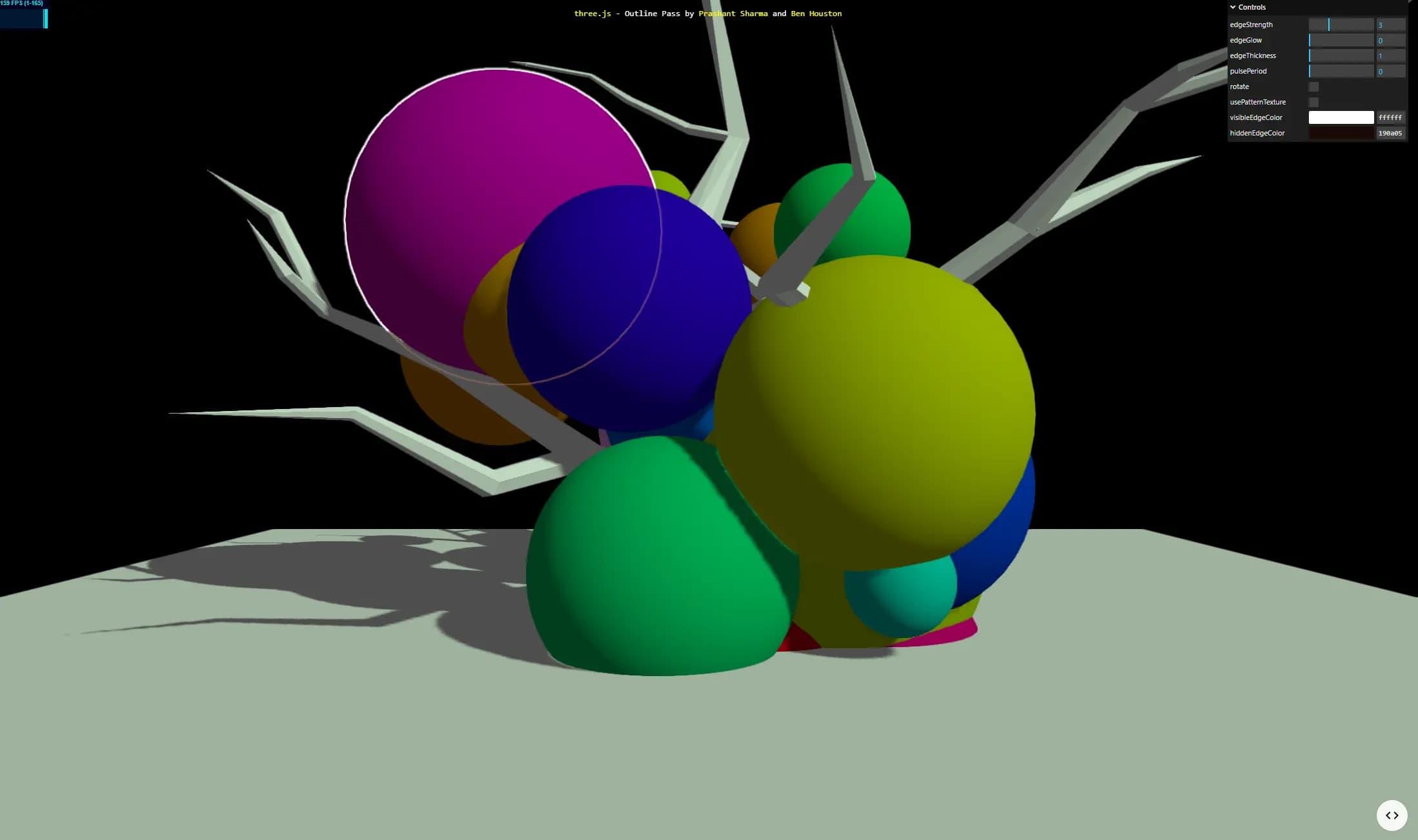 source: three.js examples webgl_postprocessing_outline
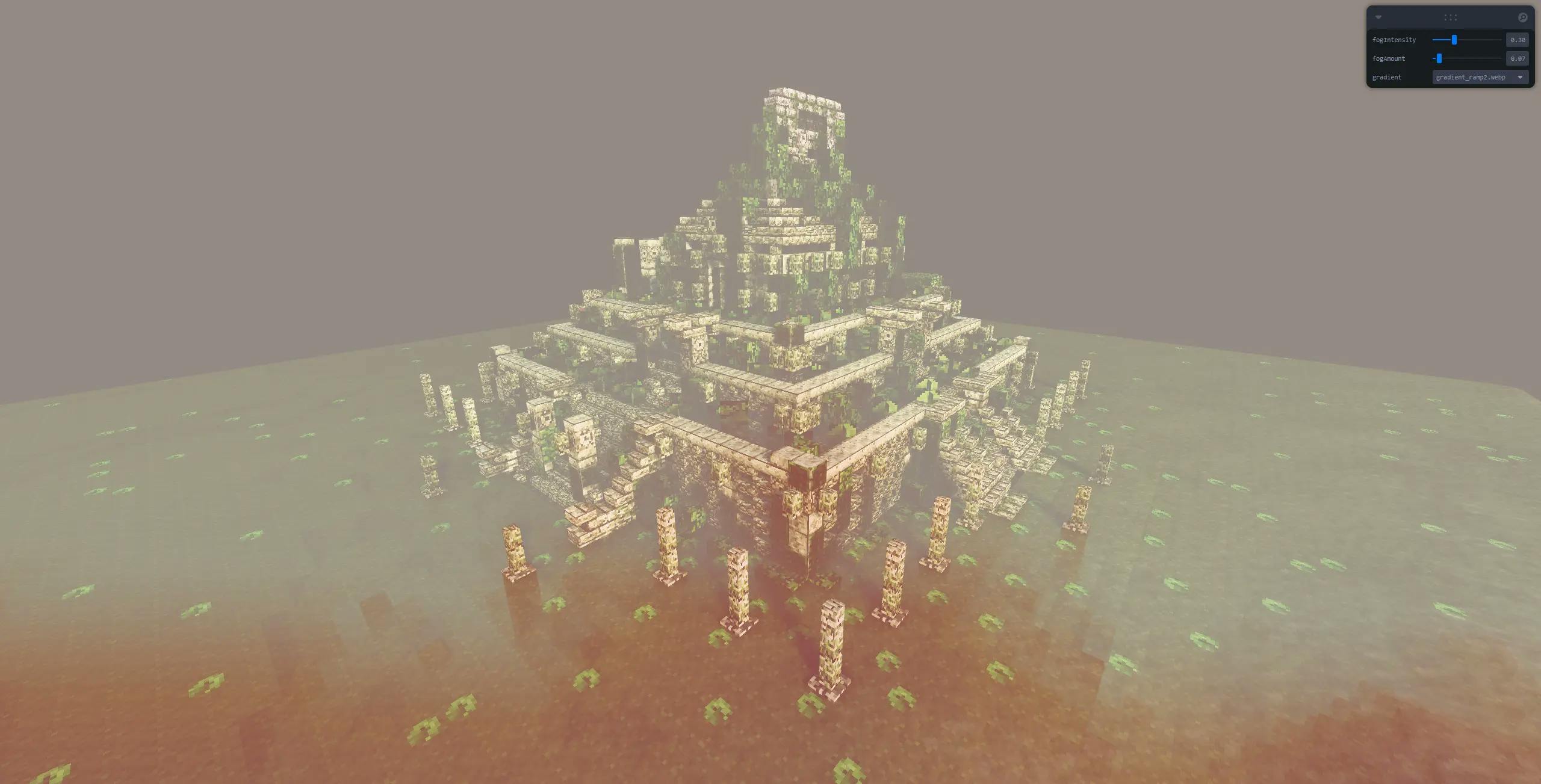
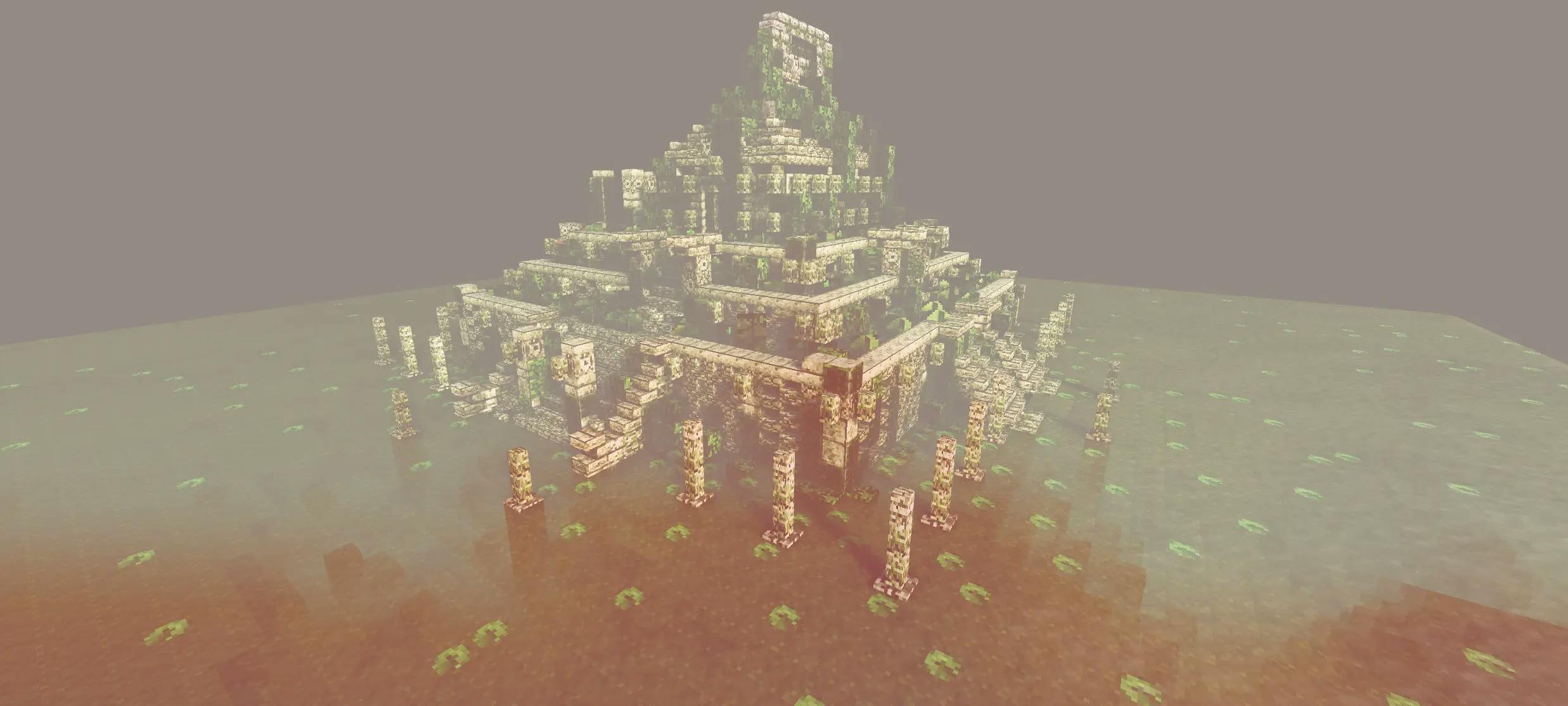
source: My fog effect: https://r3f-fog-effect.vercel.app/ (opens in a new tab)
The depth value is stored in a specific way on the RGBA channel to you need before using it in a fragment shader to unpack the channels to get a float depth
How does it look ?
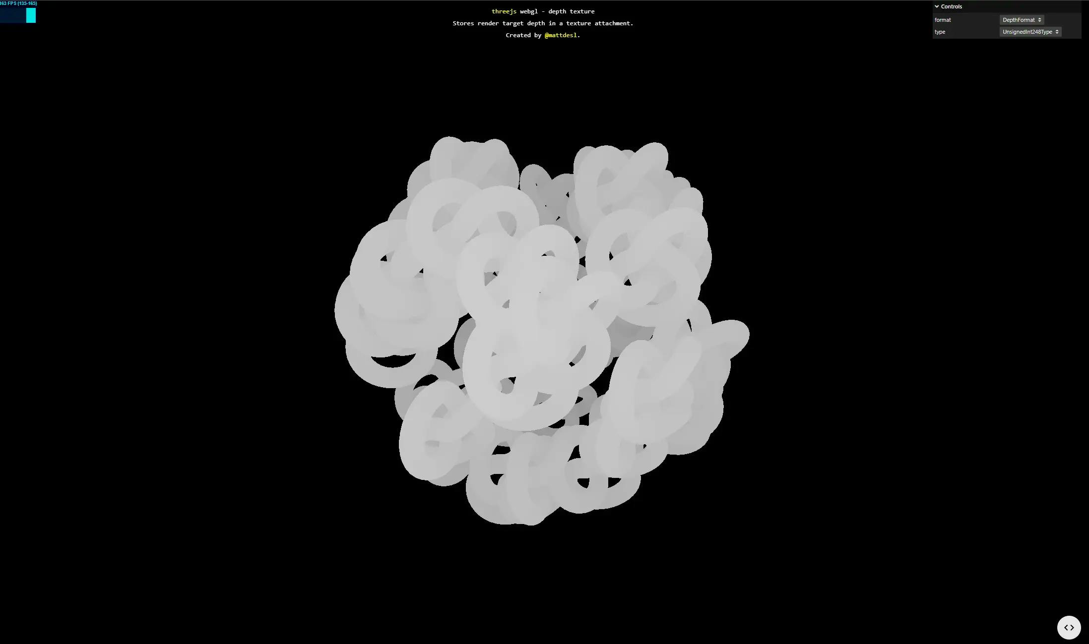 source: three.js examples webgl_depth_texture
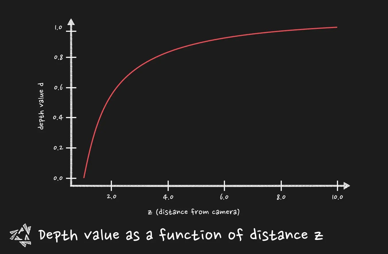
The closer you are from the near plane the whiter you get. The further you are from the camera, the darker it gets. The depth value is contained between 0 and 1.
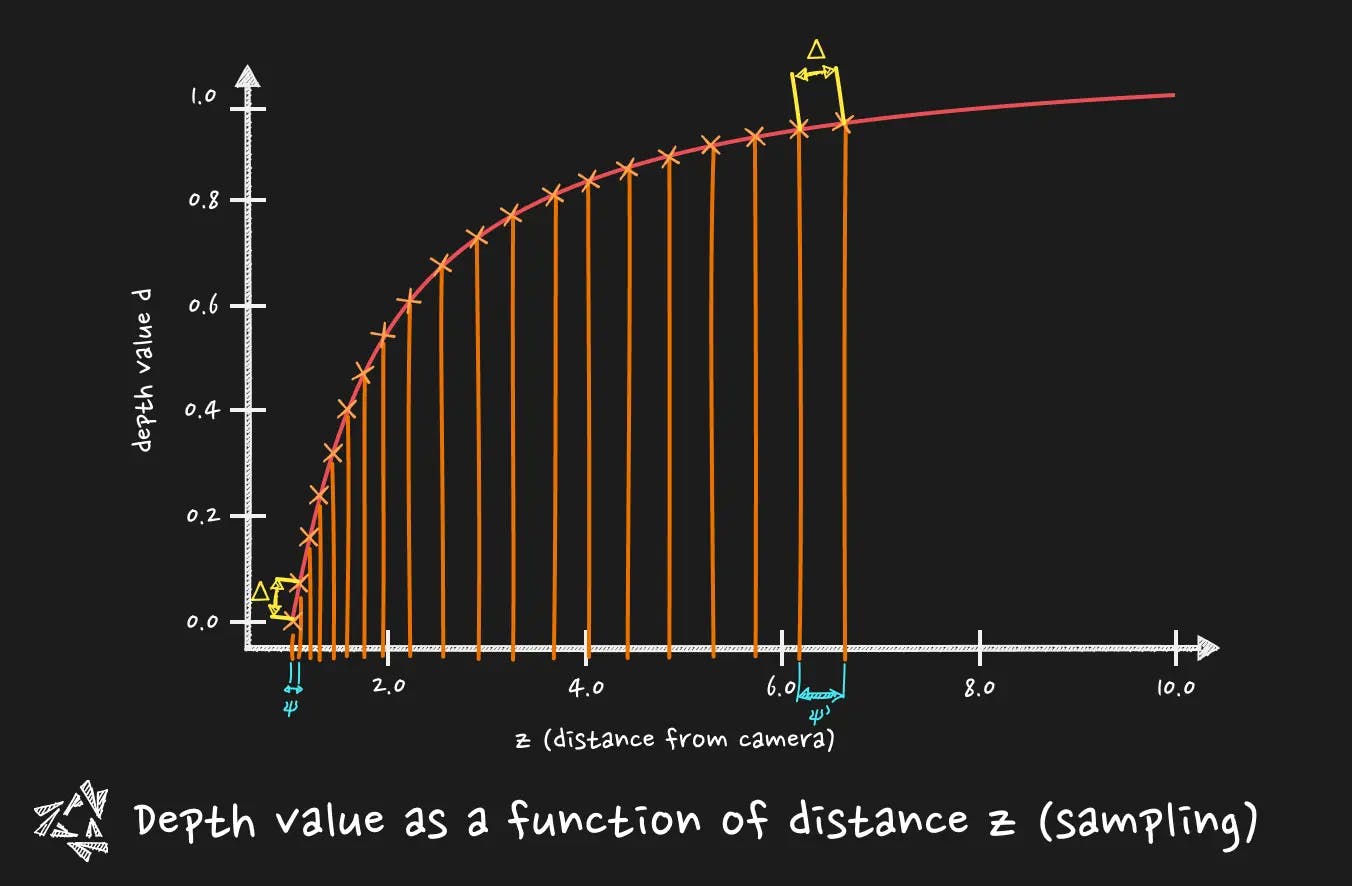
You need to pay attention that the depth buffer is not linear. It means that the growth of the depth is not distributed evenly between the near and the far plane of the camera. Remember when I talked about the magnitude of the required change in the near plane and far plane ? It is where it becomes tricky.
This characteristic is very handy when it comes to fighting the z-fighting (you did not see it coming, don't you?). Z-fighting for people not aware of it is this on the left :
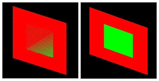
A slight change in the near plane can improve dramatically the precision and then solve the z-fighting (that bother us in particular for near objects). This is why the depth buffer non linear nature is cool, it concentrates the precision on objects that are near, and it is even more important when it comes to float precision problems.
Where it falls short, it is when you need a linear way of reading the depth. For post-processing. For instance, for a fog post-processing effect, you want your effect at first to be based on a linear Z distance from the camera. This way the fog is progressively thicker on screen based on a real distance. It is where we need to calculate the Z coordinate from the depth in view space (a.k.a how far is the object from the camera.)
Captain ! To the view space ! 👨🚀
We need to understand that the depth value is given in a space. Which space will you say ? The clip space. What is the clip space ?
If you are familiar with vertex shader code, you do often something like :
gl_Position = projectionMatrix * viewMatrix * modelMatrix * vec4(position,1.0)
Basically, you are step by step, migrating your initial geometry position from 3D space to 3D space, until you get to a space that you will be able to display on screen, your scene.
Hm?
Let's make it slow.
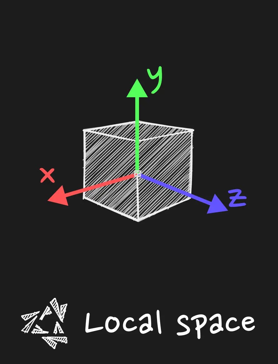
Local space
The local space is the space in which the coordinates are relative to the local origin of the object.
Basically it is your geometry in your bufferGeometry in three.js. All the vertices have an entry in the buffer, and it is the position relative to the origin of the object.
Model space or World Space
When you multiply the position by the model matrix, you get the position in the world space. It means that the vertex coordinates are relative to the origin of the world (let's say the center of the scene). Moreover, if you have your object in a group, the model matrix will be the multiplication of every parents of your object until the root of the scene. This is particularly useful when you want to knock the object off its axle for particular rotation. You can group the object with its position offset in the group, and the origin of this group will be the pivot point of the object. We go out of the topic but remember that every groups that encapsulate the object will be taken into account when you multiply the model matrix. It is given by three.js already so you have nothing to do, just multiply it.
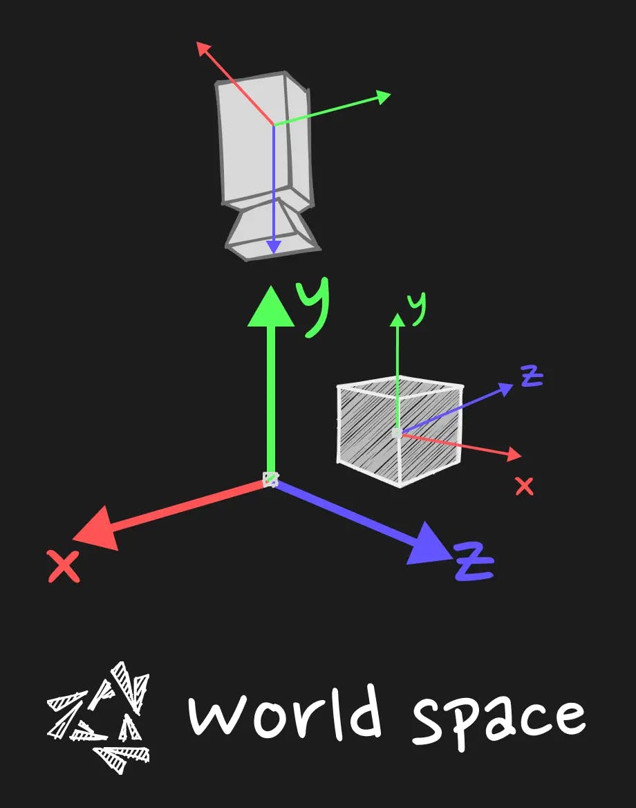
View Space
The view space is the space where the coordinates of our geometry, after being interpretated through the prisma of the world origin, will be interpreted through the prisma of the camera.
This is the space where the coordinates are expressed in relation to the position of the camera.

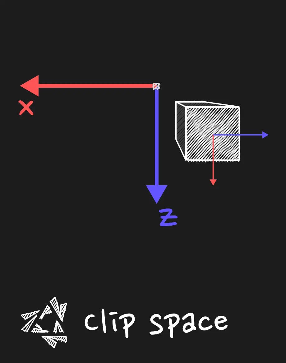
Clip Space
Then, we project the view space coordinates by taking in account the parameters of the camera (like the field of view, the aspect ratio, the near and far plane) to get the clip space coordinates.
This is what is required in the vertex shader output to go further in the pipeline. There is also an algorithm that is used to discard what is outside of the frustum of the camera.
Local space
The local space is the space in which the coordinates are relative to the local origin of the object.
Basically it is your geometry in your bufferGeometry in three.js. All the vertices have an entry in the buffer, and it is the position relative to the origin of the object.
Model space or World Space
When you multiply the position by the model matrix, you get the position in the world space. It means that the vertex coordinates are relative to the origin of the world (let's say the center of the scene). Moreover, if you have your object in a group, the model matrix will be the multiplication of every parents of your object until the root of the scene. This is particularly useful when you want to knock the object off its axle for particular rotation. You can group the object with its position offset in the group, and the origin of this group will be the pivot point of the object. We go out of the topic but remember that every groups that encapsulate the object will be taken into account when you multiply the model matrix. It is given by three.js already so you have nothing to do, just multiply it.
View Space
The view space is the space where the coordinates of our geometry, after being interpretated through the prisma of the world origin, will be interpreted through the prisma of the camera.
This is the space where the coordinates are expressed in relation to the position of the camera.
Clip Space
Then, we project the view space coordinates by taking in account the parameters of the camera (like the field of view, the aspect ratio, the near and far plane) to get the clip space coordinates.
This is what is required in the vertex shader output to go further in the pipeline. There is also an algorithm that is used to discard what is outside of the frustum of the camera.
What comes down the pipeline then ? ⚙️
I need to precise something about Clip space and in particular the w value of the vec4 coordinates. The clip space is not really homogeneous in the sense that the w value is not always 1.0 after projection. It is used to make the perspective division. It is a division of the x, y and z coordinates by the w value. It is used to get the NDC (Normalized Device Coordinates) space. It is a space where the x, y and z coordinates are between -1 and 1. It is the space where the coordinates are ready to be displayed on the screen. This step is not done in the vertex shader, it is done in the pipeline after the vertex shader. Since we are given some value and we would want to get back to the view space, we need to be careful.
Getting back to our depth value 🤔
Let's place ourselves in the fragment shader. The depth value is not very useful for some postprocessing given its current state. We need to get back to view space to work on a z-coordinate that is linear. The projection and perspective division have been already done in the pipeline to get to the level of the fragment.
We can use the inverse projection matrix to get back there, but there is a bit of work to do before.
What we need to cook the linear depth value z, is to simplify:
- the screen coordinates, that are given between 0 and 1.
- the depth value, that is given between 0 and 1.
What is problematic is that the 0 to 1 range is not a range on which any of the space we saw before is based on. We need to get back in the NDC (or the normalized clip space in some sense) and from there we can inverse the projection.
Preparing the NDC coordinates
Let's assume that we have an unpacked depth value and the UVs.
Apply the inverse projection matrix
We remove the projection and we have ensured that the coordinates were in [-1,1] range to be sure to get back to the real view space we had previously.
Normalize the value
We divide by w to get back to a w equal to 1.0. If you have remarked, we always ensure that the w is 1.0. It is what we call the homogeneous coordinates.
You could ask yourself, why we never bother to divide our coordinates by w in the vertex shader before using it inside it? It is because the rigid transformation like translate, rotate, scale, and the viewMatrix transformation are not affecting the w value. In a world where the transformation where disturbing the value, it would be necessary to normalize the value before using it in the vertex shader. It is what we need to do when calculating things with normal vector analogously, we always ensure that our vector is unit vector before extrapolating things with it. It is only the projection matrix that is affecting the w value. I hope it solves some confusion about the w value.
Now that we have the linear depth value, we can use this knowledge to craft cool fog post-processing effect.
Fog post-processing effect in three.js 🌫️
We will use postprocessing library and the react-three-fiber version of it to create a fog post-processing effect.
This makes it easier to get the value from the depth buffer and to use it in a fragment shader and directly apply it in the postprocessing pipeline.
It is also a way to learn a production ready way of using the knowledge we have acquired.
npm i postprocessing @react-three/postprocessing and let's go for a quick adventure.
The original shader that we will build comes from Godot Shaders (opens in a new tab)
Creating the Effect pass
We will extend the Effect class from the postprocessing library to create our own effect.
Add the necessary uniforms and depth parameter
gradientis a texture that will be used to color the fog.fog_intensityis a float that will be used to control the intensity of the fog.fog_amountis a float that will be used to control the amount of fog.cameraInverseProjectionMatrixis the inverse projection matrix that we talked before.
Fragment shader
The step of converting the depth value to a linear z value is given by the special function from postprocessing library getViewZ.
The fog_intensity is used to control the opacity of the fog.
The fog_amount is used to control the distance at which the fog will start to appear( in conjunction with the linear depth value.
The fog color is given by a color ramp picture given as a texture.
Create the Effect pass for the Effect composer
We will then make the GradientFogEffect a react component that will be used in the EffectComposer of the scene in react three fiber.
Build the scene and use the fog with react three fiber
We will use the EffectComposer provided by react-three-postprocessing to add the fog effect to the scene.
Be careful to use the right EffectComposer. There is one provided by react-three-fiber that is just a wrapper for the one in three.js. That is not this one that we are using for crafting the effect.
Optionally, we will use the leva library to control the fog parameters.
Result
You can see and play with this code here :
What to bring back home
In this post, we've explored the depth buffer in Three.js and React Three Fiber, starting from the basics of camera theory to implementing a fog post-processing effect. This journey through 3D rendering concepts and their application shows just how much depth and immersion can be added to your web projects. Whether you're deepening your understanding or applying these techniques for the first time, there's always more to learn and room to grow.
Your experiments and projects contribute to the vibrant tapestry of web development and 3D graphics. So, what's your take? Have you tried implementing these techniques in your work? Any challenges or exciting discoveries? I'd love to hear about your experiences and insights. Share your thoughts and feedback on Twitter (opens in a new tab), and let's keep the conversation going. The digital realm is continually evolving, and together, we can push together the boundaries of what's possible in 3D web development.